News
28 May 2019

Radio Microphones or “How Did I Get Stuck With This Job!”
Subscribe to CX E-News
 HISTORY
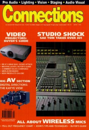
The following item appeared in Connections Magazine, March 1999, p.42, followed by a wireless systems Buyers Guide and Radio Spectrum Guide for Australia. View the Feature in full here (PDF)
Radio Microphones
(Sub-titled “How Did I Get Stuck With This Job!”)
by John Matheson.
I learned a lot of tricks in those early years, and every one of them was essential to keep the radios going. Sometimes I think that today’s diversity and noise reduction systems have made radios so easy to use that we rarely get the best performance out of them; we’ve become lazy about everything that counts.
I could write a page on why each of these tips is important. Ignore these at your peril!
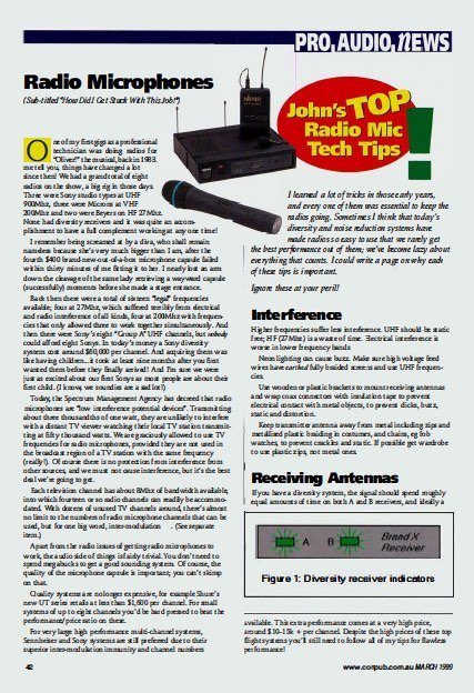
One of my first gigs as a professional technician was doing radios for “Oliver!” the musical, back in 1983. Let me tell you, things have changed a lot since then! We had a grand total of eight radios on the show, a big rig in those days.


Three were Sony studio types at UHF 900Mhz, three were Microns at VHF 200Mhz and two were Beyers on HF 27Mhz. None had diversity receivers and it was quite an accomplishment to have a full complement working at any one time!
I remember being screamed at by a diva, who shall remain nameless because she’s vey much bigger than I am, after the fourth $400 brand-new-out-of-a-box microphone capsule failed within thirty minutes of me fitting it to her.
I nearly lost an arm down the cleavage of the same lady retrieving a wayward capsule (successfully) moments before she made a stage entrance.

Back then there were a total of sixteen “legal” frequencies available; four at 27Mhz, which suffered terribly from electrical and radio interference of all kinds, four at 200Mhz with frequencies that only allowed three to work together simultaneously.
And then there were Sony’s eight “Group N’ UHF channels, but nobody could afford eight Sonys.
In today’s money [1999] a Sony diversity system cost around $60,000 per channel. And acquiring them was like having children .. .it took at least nine months after you first wanted them before they finally arrived! And I’m sure we were just as excited about our first Sonys as most people are about their first child. (I know, we soundies are a sad lot!)
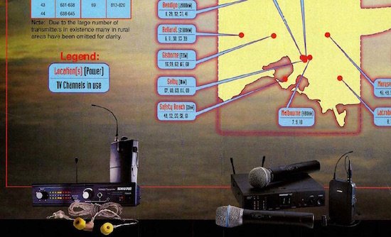
Today, the Spectrum Management Agency has decreed that radio microphones are “low interference potential devices”. Transmitting about three thousandths of one watt, they are unlikely to interfere with a distant TV viewer watching their local TV station transmitting at fifty thousand watts.
We are graciously allowed to use TV frequencies for radio microphones, provided they are not used in the broadcast region of a TV station with the same frequency (really!). Of course there is no protection from interference from other sources, and we must not cause interference, but it’s the best deal we’re going to get.
Each television channel has about 8Mhz of bandwidth available, into which fourteen or so radio channels can readily be accommodated. With dozens of unused TV channels around, there’s almost no limit to the numbers of radio microphone channels that can be used, but for one big word, inter-modulation . (See separate item.)
Apart from the radio issues of getting radio microphones to work, the audio side of things is fairly trivial. You don’t need to spend megabucks to get a good sounding system.
Of course, the quality of the microphone capsule is important; you can’t skimp on that.
Quality systems are no longer expensive, for example Shure’s new UT series retails at less than $1,600 per channel. For small systems of up to eight channels you’d be hard pressed to beat the performance/price ratio on these.
For very large high performance multi-channel systems, Sennheiser and Sony systems are still preferred due to their superior inter-modulation immunity and channel numbers c.vailable. This extra performance comes at a very high price, around $10-15k + per channel.
Despite the high prices of these top flight systems you’ll still need to follow all of my tips for flawless performance!
Interference
Higher frequencies suffer less interference. UHF should be static free; HF (27Mhz) is a waste of time. Electrical interference is worse in lower frequency bands.
Neon lighting can cause buzz. Make sure high voltage feed wires have earthed fully braided scree:1s and use UHF frequencies.
Use wooden or plastic brackets to mount receiving antennas and wrap coax connectors with insulation tape to prevent electrical contact with metal objects, to prevent clicks, buzz, static and distortion.
Keep transmitter antenna away from metal including zips and metallised plastic braiding in costumes, and chains, eg fob watches, to prevent crackles and static. If possible get wardrobe to use plastic zips, not metal ones.
Receiving Antennas
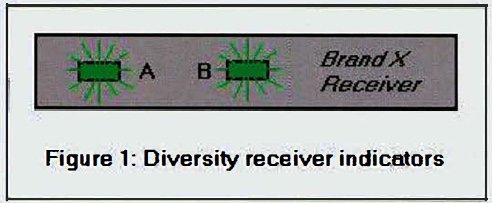 If you have a diversity system, the signal should spend roughly equal amounts of time on both A and B receivers, and ideally a lot of time on A and B together. If not, one or both of your receiving antennas are faulty or poorly sited.
Never assume that both receiver antennas in diversity systems are working properly. Disconnect each antenna in turn at the input to the receiver and “walk test” the transmitter through the whole performance area. If it doesn’t work properly on each antenna separately, fix the problem or you’re headed for trouble. For a large performance area, site receiver antennas on opposite sides to ensure you always have one strong signal.
Try to position antennas with line-of-sight to transmitters. Particularly avoid having metal structures between units. Tilting the receiving antenna off vertical will help prevent dropouts caused by standing waves.
For maximum antenna signal, keep antennas clear of other metal objects by at least the length of the antenna’s elements.
Low loss cable is essential for UHF antenna cable extensions, but not for VHF except for long runs, eg cross stage. Use only crimp style connectors of the correct type for antenna leads for reliable operation.
And use 50 antenna cable, not 75 television coax, or you will lose signal at every cable junction because of impedance mismatch.
Antenna distribution systems work well, but make sure that the distributor has unity gain if using receivers designed for “on unit” ariels. Excessive gain will overload the input causing interference.
Testing
If possible, turn off noise reduction systems whilst “walk testing” transmitters. The noise reduction system masks dropout problems, which is what it is supposed to do, but it doesn’t help you find the best locations for receiving antennas. If you can’t turn it off, hum into the microphone. Listen for swishes and splats; if you’ve done you job properly, you won’t get any.
Test every transmitter on stage before every performance. Don’t turn them off after testing unless you plan to test them again.
Don’t use kid gloves when testing transmitters – they have to stand up to the worst treatment during a performance. It is better they break before the performance, not during it. Yank all leads, wiggle all connectors, bang all cases and have all transmitters on together.
Tape or cover all controls to prevent “helpful” performers buggering things up!
Batteries
 Use only brand name alkaline batteries. Test battery voltage in situ with a digital voltmeter and with transmitter “on” before and after it has run for fifteen minutes. If the voltage has dropped by more than a small amount you have a dud battery or a dud transmitter.
Use rehearsals to test ultimate battery life. You may have to change batteries at interval, after every performance or after every second or third performance depending on transmitter and battery type.
Some transmitters do not have power stabilising circuits and performance drops as batteries are used up; see note on batteries above.
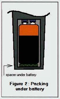
Nine-volt batteries vary in length. Short ones may need a spacer to ensure good contact with the battery terminals and to prevent them rattling. Use a piece of cardboard.
 Body-pack Transmitters
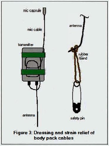
Vertical transmitter antennas work better than horizontal ones.
Run antenna cable straight down from the transmitter case. Do not fold back across transmitter. Use a longish rubber band attached to the end of the antenna and pinned to clothing to keep antenna extended without strain.
Sweaty skin reduces transmitted power at UHF. Keep antenna away from skin if possible, eg on outer layers of clothing.
Coil excess microphone cable and tape it to the transmitter case. (NB: Except where the microphone cable is also the antenna.) Run microphone cable away from transmitter in opposite direction to antenna.
Lapel Microphones
A drop of sweat can seal a capsule, blocking sound. Try to have front of capsule hanging downwards. Watch out for strands of hair, which can penetrate the microphone mesh and cause crackling.
Adjustments
Read the owner’s manual before adjusting squelch levels and gain for optimum Performance. Correct squelch adjustment is really important in multi-channel systems.
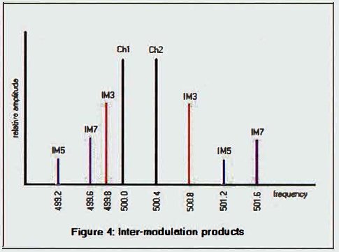
Inter-modulation Explained
Mixing two radio frequencies in a non-perfect amplifier causes the generation of distortion components called inter-modulation products.
These new junk frequencies occur at the sum and difference of the two original frequencies. It happens at the output stage of transmitters, such as when one transmitter is in close proximity to another and radiates into its output stage, in the input stages of receivers, and in antenna booster amplifiers.
 First order sum and difference products (f1 + f2, f1 – f2) will not cause a problem unless the difference happens to fall near to 10.7Mhz, which is used as an intermediate frequency in the modulation/demodulation process.
For example, don’t expect 500.0Mhz and 510.7Mhz to work happily together.
Third (2f1 – f2, 2f2 – f1), fifth (3f1 – 2f2, 3f2 – 2f1) and seventh (4f1 – 3f2, 4f2 – 3f1) order inter-mod difference products do cause problems. Higher order inter-mods can usually be ignored. For example, if we have on transmitter at 500.0Mhz and one at 500.4Mhz, the following inter-mod frequencies will be generated: 499.2, 499.6, 499.8, 500.8, 501.2 and 501.6Mhz.
None of these frequencies can be used for additional channels at the same time as 500.0 and 500.4 without risk of interference. So a two-channel system with a nominal 0.4Mhz spacing is already using up 2.4Mhz of bandwidth. In reality a clever frequency allocation will interleave additional channels between all these problem frequencies.
Because every combination of frequencies present will generate inter-modulation products, the number goes up exponentially as more channels are added, so that for a 13-channel installation there are already more than 1200 frequencies to be avoided.
There are two things that really differentiate a good radio microphone system from an average one: the quality of filtering in the output stage of the transmitter and the input stages of the receivers; and the linearity of all amplification stages in transmitters, boosters and receivers. Good electronics (usually= more expensive) means more channels can be crammed together with less risk of interference.
John Matheson designs electro-acoustic systems for Bassett Acoustics. Call him on +61 8 8363 1000.
From Connections Magazine, March 1999, p.42.
CX Magazine – Entertainment technology news and issues for Australia and New Zealand – in print and free online www.cxnetwork.com.au
© CX Media
Subscribe
Published monthly since 1991, our famous AV industry magazine is free for download or pay for print. Subscribers also receive CX News, our free weekly email with the latest industry news and jobs.
Recent posts